SDVOE
AV Over IP Solution
1: OVERVIEW
IPS delivers a true 4K AV over IP solution with zero compression and zero latency, featuring unmatched I/O density, shared infrastructure, flexible I/O, and built-in scalability. The IPS-M AVLink controller provides an efficient way to configure the AV over IP system with IPS-TX and IPS-RX devices. As an API-based command server, IPS-M allows easy configuration of connected devices via a PC and monitors the status of each device across the network.
Figure 1-5 IPS-M

Figure 1-1 IPS-TF
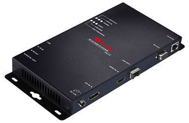
Figure 1-2 IPS-TC
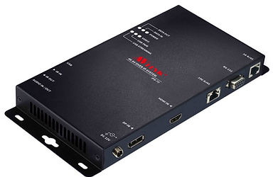
Figure 1-3 IPS-RF
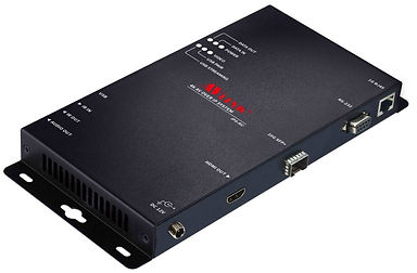
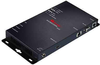
Figure 1-4 IPS-RC
Packing

2: FEATURES
HDMI Input
-
True 4K/60 4:4:4 and HDR
-
HDMI 2.0 compatible input port
-
Support HDCP 1.4 and 2.2
HDMI Output
-
True 4K/60 4:4:4 and HDR
-
HDMI 2.0 compatible output port
-
Support HDCP 1.4 and 2.2
10G-SFP+Transport
XFI interface
-
10GBASE-T 100m with Cat 6a cable
-
Multi-mode fiber 300/500m with OM3/OM4 fiber
-
Single-mode fiber up to 30KM
Video Routing
-
Lightweight 1.4 to 1 artifact-free compression
-
Time to switch between sources in under 100 milliseconds.
Audio Routing
-
Lossless audio transmission
-
HDMI downmixed stereo channel
1G Control Interface
-
Extension of Gigabit Ethernet data network
-
Built-in Ethernet switch connects 1GbE Ethernet to 10GbE interface
-
Device Control
USB Routing
-
Up to 480 Mbps
RS232 Routing
-
Baud rate up to 115200
-
Unicast and broadcast routing between devices
-
Serial data routing between multiple devices
IR Routing
-
IR data routing between multiple devices
Video Scaling
-
Upscaling (TV wall) and downscaling (Multi-view)
-
Color space, Chroma sampling, and frame-rate conversion
-
Multi-source video compositing
-
Video wall processing with bezel correction and display synchronization
3: SPECIFICATIONS
IPS-TX/RX Specifications:


IPS-M Specifications:

4: COMPONENTS
4.1 Front Panel
These LEDs on the front panel specify the status of Power, Video data, Network packet, and USB routing.

Figure 4-1 IPS-TX front panel
Figure 4-2 IPS-RX front pane
Figure 4-3 IPS-M front panel
LED Indicators:
POWER:
-
Yellow Bright: System power-on successfully.
-
Off No power or power-on fail.
DATA IN / DATA OUT:
-
Yellow Blink: Data transmitted and received through Ethernet.
-
Off: No Data transmit or received through Ethernet, or without attaching an Ethernet cable.
VIDEO:
-
Yellow Bright: Video signal is stable.
-
Off No Video Source or Video signal is unstable, or stop Video Streaming.
USB PAIR:
-
Yellow Bright: USB chip is paired.
-
Yellow Blink: USB chip is not paired.
-
Off No USB chip/FW loaded
USB STREAMING:
-
Yellow Blink: USB data traffic present.
-
Off No USB data traffic present.
Connectors:
USB Port:
-
IPS-TX (LEX): Connected to the USB host (e.g., PC) within the 5-meter limitation.
-
IPS-RX (REX): Connected to the actual USB device within the 5-meter limitation.
IR IN / IR OUT:
-
Connected to Infrared devices (e.g., Infrared remote, receiver, or blaster)
Audio IN / OUT Port (IPS-TX):
-
Connected to the speaker or audio source.
Audio OUT Port (IPS-RX):
-
Connected to the speaker.
4.2 Rear Panel
IPS-TX:
IPS-TX supports 2 video interfaces on the rear panel, including HDMI and DisplayPort (DP). It supports a 10G network interface including either 10GBaseT or SFP+.

Figure 4-4 IPS-TC rear panel
Figure 4-5 IPS-TF rear panel
IPS-RX:
IPS-RX only supports HDMI output on the rear panel. It supports a 10G network interface, including either 10GBaseT or SFP+.

Figure 4-6 IPS-RC rear panel
Figure 4-7 IPS-RF rear panel
IPS-M:
IPS-RX only supports HDMI output on the rear panel. It supports a 10G network interface, including either 10GBaseT or SFP+.

Figure 4-8 IPS-M rear panel

5: CONNECTION
5.1 IPS-TX & IPS-RX Connections
With multiple IPS-TX and IPS-RX units, AV signal sources and output destinations can be easily switched and configured. The built-in audio/video interfaces transmit signals over the 10G network to the designated displays. Users can control output templates and manage configurations for specific displays across multiple signals.
Additionally, each IPS-TX and IPS-RX supports independent routing for data streams. Video signals can be sent to a designated IPS-RX, while audio signals can be routed to additional IPS-RX units. This capability provides flexible configuration options for both video and audio distribution.

5.2 IPS-TX & IPS-RX for KVM
The IPS-TX & IPS-RX supports the KVM Switch application:
-
Support USB 2.0 at full 480Mbps bandwidth for the control command.
-
10 Gbps for more USB applications.
Not only keyboard and mouse, but flash, web cameras, and more

5.3 IPS-TX & IPS-RX for Video Wall
The Video Wall mode allows you to output the signal source of a single video through multiple displays.
-
The video source is connected to the HDMI interface of a single IPS-TX. Each display is connected to the HDMI interface of each IPS-RX.
-
IPS-TX transmits video signals to each IPS-RX via a 10G Ethernet switch.
IPS-RX supports crops and scales display features; the built-in scaler engine is used to cut out a single video to display the cropped area on the screen.

5.4 IPS-TX & IPS-RX for Matrix Switch
The input image of each IPS-TX can be freely switched to the specified IPS-RX for output. Through the routing configuration of IPS-M, the video signal is rendered seamlessly on a realistic screen.

5.5 IPS-TX and IPS-RX for Multi-view
The multi-view feature allows you to combine multiple video signals into a specified screen. You can see multiple different video signals or PIP (Picture in picture) on one screen.

5.6 Audio Routing
Through IPS-TX and IPS-RX, Digital and Analog audio signals can be output individually, described as below:
When the Analog Audio of IPS-TX is specified for "Audio output":
The Analog Audio and HDMI output of IPS-RX, Analog Audio of IPS-TX can be used as an audio output to transmit the audio signal that comes from the HDMI input of IPS-TX.

When the Analog Audio of IPS-TX is specified for "Audio input":
The Analog Audio and HDMI audio input of IPS-TX can be transmitted to the HDMI output of IPS-RX and the Analog Audio output, respectively.
